3D Scanning Engineering in Broome
Precision Engineering, 3D LiDAR Scanning, Modelling & Drafting for WA’s Northwest
Broome isn’t just a tourism icon — it’s a strategic industrial gateway for the Kimberley and wider Northwest region. With its mix of coastal infrastructure, aviation hubs, port operations, aquaculture, remote-area logistics, defence presence, and fast-growing construction and industrial service sectors, Broome demands accurate engineering, resilient design, and clear digital documentation.
Hamilton By Design supports Broome and the Northwest with 3D LiDAR laser scanning, advanced engineering, 3D CAD modelling, and fabrication-ready drafting — giving local operators, fabricators, builders, and councils the precise data they need to design, upgrade and maintain complex assets.
Why Broome Is Unique for Engineering & 3D Digital Capture
Broome presents engineering challenges unlike any other region in Australia:
1. Cyclone-Prone Coastal Conditions
Infrastructure must withstand extreme weather, high winds, saltwater exposure and corrosion cycles.
2. Remote-Region Logistics
Every upgrade, installation or fabrication effort must be done right the first time — rework is costly due to distance, travel, and mobilisation requirements.
3. Diverse Infrastructure Portfolio
Broome’s economy spans:
- Port and marine services
- Aquaculture and pearling facilities
- Aircraft/airport operations
- Utilities and water assets
- Community and tourism developments
- Defence and government infrastructure
Each requires accurate as-built documentation and engineering certainty.
4. Heritage, Environment & Cultural Sensitivity
Design and construction must consider local heritage, Indigenous stewardship, and coastal environmental constraints.
This makes 3D scanning and digital engineering essential for project planning, structural upgrades, fabrication works, and long-term maintenance.
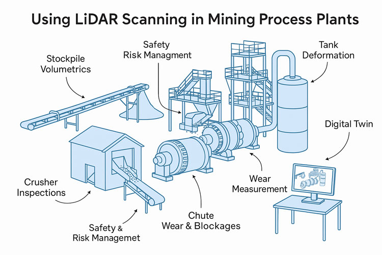
High-Accuracy 3D LiDAR Scanning for Broome Projects
Hamilton By Design provides millimetre-accurate scanning to document existing structures, marine assets, foundations, terrain, utilities, steelwork, and equipment layouts.
Learn more about our scanning capabilities:
3D Laser Scanning
3D scanning reduces site risk, improves precision, and allows remote teams to view and measure the site digitally without multiple visits — ideal for Broome’s remote context.
We support:
- Wharf and jetty upgrades
- Aquaculture processing & pipeline systems
- Industrial workshops
- Remote utilities infrastructure
- Structural condition assessment
- Coastal facility expansion
- New-build design coordination
3D CAD Modelling — Digital Twins for Better Engineering Decisions
After scanning, our team converts point-clouds into detailed mechanical, structural and civil 3D models.
Learn more:
3D CAD Modelling
These models support:
- concept layouts
- clash detection
- fabrication planning
- equipment integration
- structural and mechanical coordination
- tender documentation
- regulator submissions
For Broome operators, digital models mean fewer delays, improved communication, and precise fabrication — even when suppliers are hundreds or thousands of kilometres away.
Engineering & FEA for Coastal, Industrial and Remote-Region Assets
Broome assets must handle corrosion, high wind loads, dynamic forces, mechanical wear and extreme temperatures.
Hamilton By Design provides:
- structural analysis (steelwork, platforms, frames, supports)
- mechanical design for machinery, conveyors, pipework and plant equipment
- fatigue, stress, vibration and pressure modelling
- load assessments for marine and coastal assets
- design verification and documentation
Explore our analysis capabilities:
FEA Capabilities
This ensures projects in Broome are safe, compliant and resilient.
Drafting & Documentation for Fabricators, Builders & Councils
We produce complete drawing packages that Broome’s industries rely on, including:
- GAs and layouts
- Structural detailing
- Isometrics
- Workshop fabrication drawings
- As-built records
- Revision and modification documentation
Learn more:
Drafting
Our drafting aligns directly with field-accurate scan data, giving fabricators and contractors confidence from day one.

Why Broome Operators Choose Hamilton By Design
- Engineer-led scanning for accuracy, safety and context
- End-to-end capability — scan → model → engineer → draft
- Reduced travel cost due to remote digital access
- Fewer errors, clashes and fabrication issues
- Fast turnaround even for remote locations
- Proven experience in mining, marine, industrial and regional projects
Broome’s infrastructure is growing — and precise engineering is essential. With 3D scanning, modern modelling, and strong engineering expertise, Hamilton By Design helps the Northwest build better, faster and with full confidence.
Our Clients